Connecting to power and external microphone
The camera may be powered with PoE and/or through the auxiliary power cable using either a 24 VDC or 24 VAC (RMS) auxiliary power source that supports up to 71W or 85VA.
Seamless Failover
Redundant power with seamless failover is available on the PTZ camera. Seamless failover allows the camera to transition between PoE and auxiliary power sources without any interruption of camera operation. This is mainly useful if you want redundant power sources so that power will be available if one power source goes down. The axillary power source takes priority in providing power.
The Alta H6A PTZ camera does not currently support seamless failover.
To power the camera from a 24VAC supply, use the 2-pin plug in connector (supplied with the camera), connect the two power wires to the connector and plug it into camera. The connection can be made with either polarity. 18AWG or heavier wires recommended for most cable runs between the 24VAC/VDC power source and the camera. If a longer cable run is required, a wire gauge table should be consulted to ensure that the voltage at the camera does not drop outside of the specified range when the camera is operating at the maximum rated power draw.
Power supplies and external devices are connected to the camera through the power and I/O wires.
This product is intended to be powered by a UL Listed Power Unit marked "Class 2" or "LPS" or "Limited Power Source" with output rated:
- In-Ceiling Mount: 24 VAC ± 10% 55VA, or 24 VDC ± 10% 35W, or 25.5 W PoE+ IEEE 802.3 at Type 2, Class 4 compliant.
- Pendant Mount: 24 VAC ± 10%, 85VA or 24 VDC ± 10% 70W, or IEEE 802.3at Type 2, Class 4 compliant, or IEEE802.3bt Type 3, Class 6 compliant, or IEE802.3bt Type 4, Class 8 compliant* (*Using anything less than a Type 4, Class 8 PSE will result in reduced environmental and pan/tilt speed specifications).
External microphone connection
An external microphone can be connected to the camera through the supplied I/O 16-pin plug in connector. The pinout for the I/O connector is shown in the following diagram.
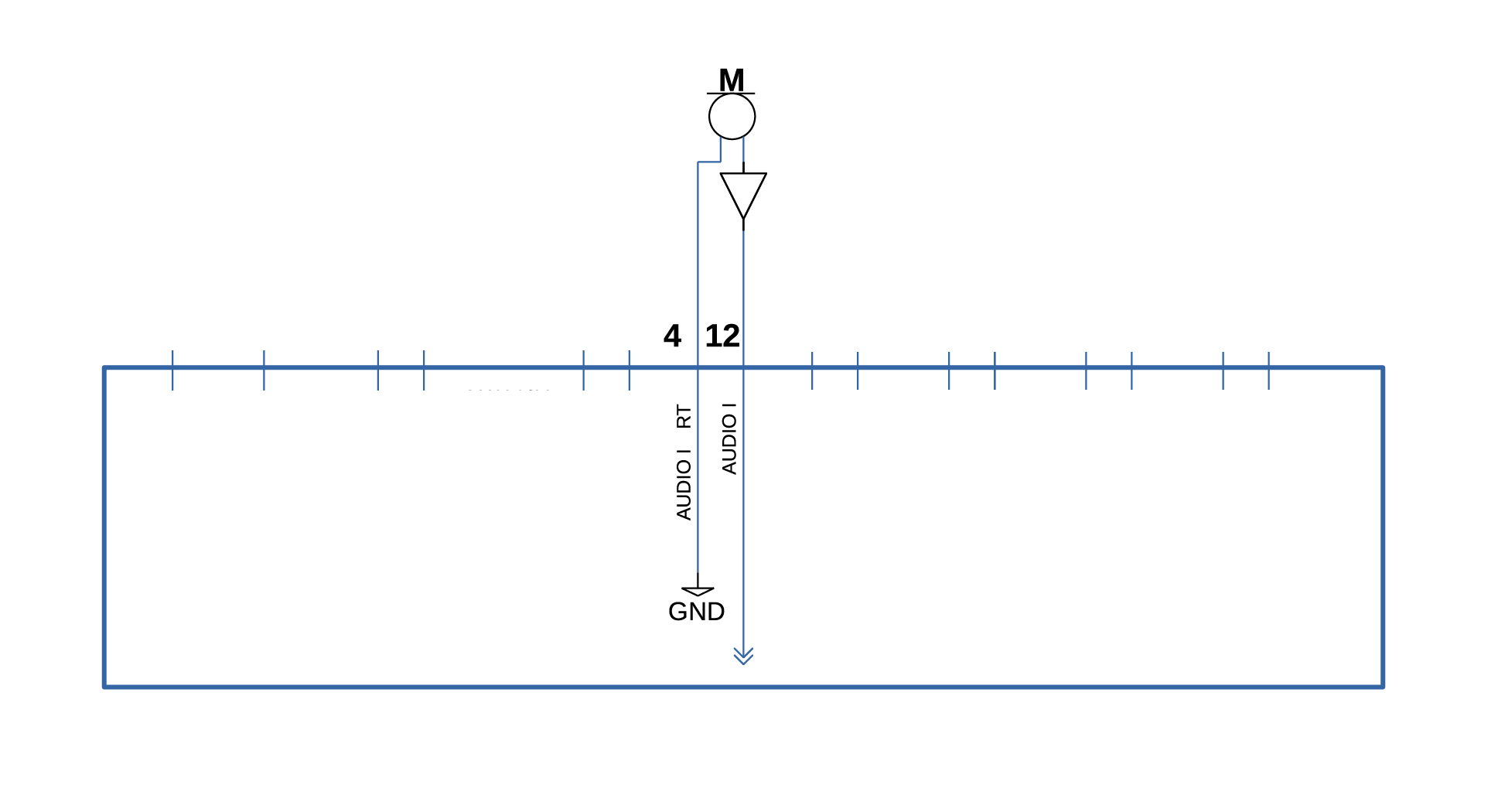
| Description | Plastic Cover Pin-Out |
| AUDIO IN |
12 |
|
AUDIO IN RETURN (GND) |
4 |