Overview
Main unit
Front View

- microSD card slots (x2)
Used for the onboard storage. The included microSD cards are sized to match the retention period for the model of purchased base unit.
-
Firmware revert button
Resets the camera to its factory default settings.
Rear View

-
Imager connection LEDs (x2)
LEDs that provide information about imager device connections. For more information, see Imager Connection LED Indicators.
-
Imager HD BNC connectors (x2)
HD BNC cable connections for connecting the modular camera main unit to up to two imager modules.
-
Micro USB port
Reserved for future use.
-
I/O connector block
Reserved for future use.
-
Ethernet port
Accepts an Ethernet connection to a network. Server communication and image data transmission occurs over this connection. Also receives power when it is connected to a network that provides Power over Ethernet.
-
Power connector block
Accepts an external DC power connection when Power over Ethernet is not available.
-
Link LED indicator
Amber LED indicates if there is an active connection in the Ethernet port.
-
Connection status LED indicator
Green LED provides information about device operation. For more information, see Connection Status LED Indicator.
Bottom View
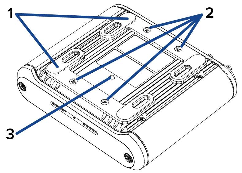
- Mounting feet (x2)
Main unit mounting feet that can be used for a tabletop installation or a wall mount. The mounting feet are removed for a DIN rail mounted unit.
-
Mounting feet screws (x4)
Screws for fastening the mounting feet to the main unit.
-
DIN rail mount screw hole
Screw hole used for fastening the DIN rail mount to the main unit.
DIN Rail Mount View
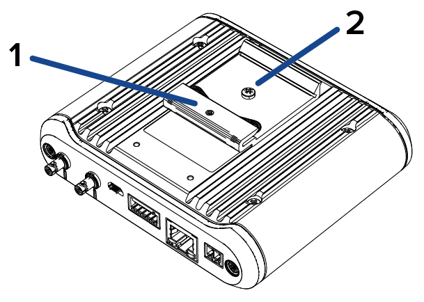
- DIN rail mount
Mount used for securing the main unit to a DIN rail. Ordered separately (BRKTMD-1001).
-
DIN rail mount screw
Screw used for fastening the DIN rail mount to the main unit.