(Optional) Mounting the Dome Camera to the Pendant Wall Mount
If the dome camera will be using the pendant wall mount, you will need to attach it to the pendant back box.
- Determine where the cables will enter the pendant wall mount.
- If the cables will be pulled from inside the mounting surface, use the cable entry hole at the rear of the pendant wall mount.
- If the cables will be coming out of an external conduit pipe, use the 3/4” NPT pipe entry hole on the bottom of the pendant wall mount.
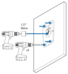
- Use the provided mounting template to drill four mounting holes into the mounting surface.
- If you are using the rear cable entry hole, also drill the cable entry hole into the mounting surface.
- Place the pendant wall mount on the mounting surface and screw it in using the user supplied screws.
Pull cables through the wall mount if using rear cable entry.

- If you are using the pipe entry hole, pull the cables through the pipe conduit then the wall mount. Next, apply thread seal tape to the pipe conduit and screw it into the pipe entry hole.
-
Remove a grommet in the back box to feed the cables through.
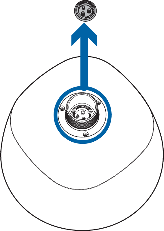
-
Screw the locknut into the back box. Tighten the locknut using tongue and groove pliers.

-
Apply the supplied Teflon tape to the threads in the back box.

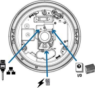
- First, feed the RJ45 cable through the grommet with the supplied insertion tool. The RJ45 cable has to be the first cable fed through the grommet.
- Two of the grommet holes are the same size and the third is different. Use the third, or smallest, hole for the power cable.
- Use the other two holes for either of the other two cables (e.g. The Ethernet cable can go into either one of the two holes that are the same size.).
- Feed an already terminated Ethernet cable through the grommet using the supplied insertion tool.

If the insertion tool is not used, then the Ethernet cable needs to be terminated with an RJ45 connector (not supplied) after being passed through the grommet.
- (Optional) Terminate the pair of power cables to the supplied, two-pin, removable header with screw down terminals.

- (Optional) Terminate the 1~16 multi-wire cable bundle to the supplied 16-pin removable header with push-in terminals.
For more information, see Connecting to power and external microphone.

- Once all of the cables are terminated (after being fed through the grommet), feed that entire bundle through the back box and seat the grommet.

- Screw the pendant back box into the wall arm and tighten.

- Connect the cables to the power supply board's (PCB's) printed circuit board assembly (PCBA) inside the bottom of the back box.
- Connect the cable for network/PoE or network. The connector on the camera is a RJ45.
- Connect the cable for auxiliary power.
- Connect the cable for the auxiliary Inputs/Outputs/Audio.